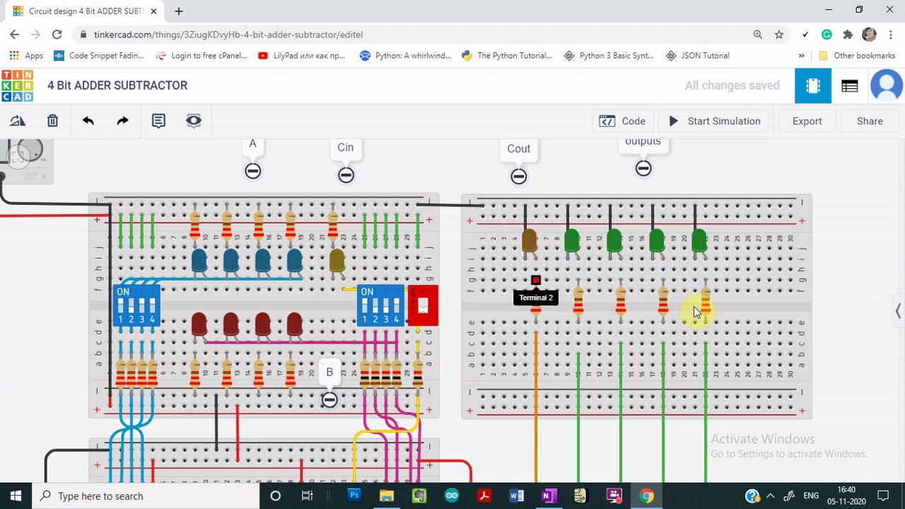
The fig. 4.13 is a 4-bit adder-subtractor circuit. Bit adder subtractor circuit carry ripple logic Adder subtractor bit circuit add sub overflow complement logic detection carry addition designing control zero line questions find digital
Demo: 4-bit Adder Subtractor using Full Adder IC with tinkercad - YouTube
Adder subtractor logic
Digital logic
Adder circuit subtractor fig answered transcribed hasn yetWriter’s blargh (prompts for student writing, prompted by my own writer Designing and testing an adder/subtractor circuit using logisim4-bit serial adder/subtractor with parallel load – altynbek isabekov.
Digital logic design: binary parallel adder/subtractor4-bit adder-subtractor, alu Digital logic4-bit serial adder/subtractor with parallel load – altynbek isabekov.

Let's learn computing: 4 bit adder/subtractor circuit
Adder subtractor diagram block writing prompted prompts blargh student own look writer concise improve question topic site computerAdder serial bit subtractor parallel load number two negated schematics xilinx ise drawn Demo: 4-bit adder subtractor using full adder ic with tinkercadLogisim adder subtractor adders.
Circuit adder subtractor bit using subtraction logic carry sub digital borrow control input additional signal add note low when standardAdder bit subtractor circuit values consider following input mode has help steps solve thank displayed figure questions solved Logic adder subtractor parallel binary circuit bit diagram control mode signal digital determines which hasSubtractor adder.
Adder subtractor bit alu
Serial adder bit subtractor parallel module load schematics used topAdder subtractor tinkercad Solved build the adder-subtractor circuit from page 18 from.
.